logo    Trolley Scan(Pty) Ltd

RFID-radar(tm)

RFID-radar - How it works

Introduction

RFID-radar is one of the most advanced RFID systems available in the world!!

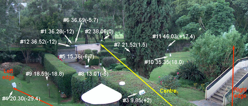
Besides identifying RFID transponders in its zone, the RFID-radar system is able to measure the range and direction of those transponders from the reader antennas.

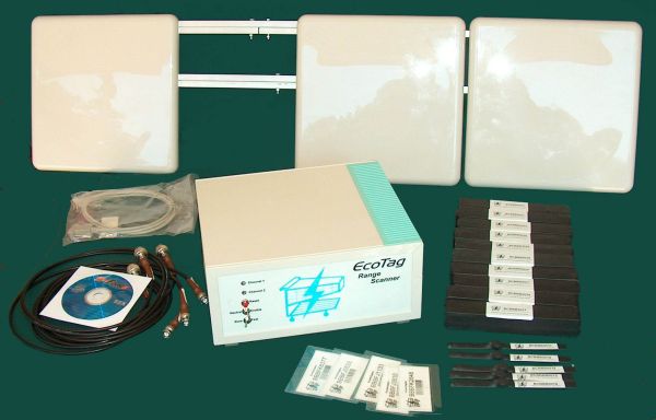
For those wanting to experiment with this new technology, Trolley Scan have provided a starter system comprising a reader, 3 Yagi antennas and 20 transponders. The system operates at UHF frequencies in the bands allocated for RFID, using electric coupled propogation properties to transfer energy from the reader to the transponder and from the transponder back to the reader.

The RFID-radar measures the path length for signals travelling from the transponder to the reader to determine range.

By comparing signals arriving at two identical receivers with closely spaced antennas, the reader is able to determine the angle of arrival of the signals from the transponder and hence the direction of that transponder from the reader.

Small system complete

The small system, slightly bigger than a mobile broadband dongle, is capable of delivering higher power for longer range operation for those countries where this is allowed, enabling the system to also be used as a research tool. The purpose of this equipment is to allow users to experiment and build systems using UHF RFID, allowing them to understand the intracacies of using RF to power transponders at a distance.

Measuring range

The radar DOES
  • Measures the length of the path the radio wave travels from the transponder to the reader.
  • Measures the angle of arrival of the incoming signal to give a range and angle to each measurement.
  • Makes all these measurements from a single location, allowing it to operate in a mobile or changing environment
  • Uses 10 kHz of radio spectrum
  • Can be set to operate at any UHF frequency in the RFID band, from 860-960MHz
  • Uses backscatter tags, that is the tags do not transmit energy, they just reflect energy from the reader back to the transmitter,at the same operating frequency as the reader's energising signal.
  • Allow many radars to be used at the same location mounted close to each other, each scanning their own zone.
  • Use low cost single chip transponders and more complex long range transponders.
  • Measure distances up to 100 meters provided the RF technology exists to operate the transponders at such a range.
  • Measure the location of multiple transponders in a zone at one time
  • Identify transponders entering its field at speeds as high as 300kph
  • Uses low RF power, from only 0.5 watts to 4 watts setable by user
  • Uses a tag-talks-first low interference protocol
  • Does not interfere with other RF users, such as cellphones.
  • Uses the same transponders that work with Trolley Scan RFID readers.
  • The radar uses a new method of measuring the radio path length of each transponder to reader path.

    The radar DOES NOT

  • Use any form of triangulation.
  • Need any form of site survey such as used in Radio fingerprinting.
  • Use any form of power density measurement such as in Multilateration.
  • Need any form of supporting wireless infrastructure such as WiFi, Bluetooth, or Wlan.
  • Need any form of satelite support such as GPS.
  • Need any form of infrared support such as infrared ranging.
  • Work at present with active tags that transmit on their own dedicated frequency.
  • Operation

    The radar has three modes of operation, namely

  • Identify immediately any new transponder entering its zone (even at speeds of 300kph).The tags identity is immediately reported with a dummy entry location.
  • Locks on to the signal from the transponder to determine its position - this takes about 20 seconds. Once location is determined the identity and position are reported.
  • Tracks movement of the transponder in its zone, reporting location of each transponder at one second intervals.
  • In the event of losing signal from a transponder for a short time, reports the estimated position based on past measurements.
  • When powering up the radar for the first time, when linked to the display program on a Win32 based computer for example.
  • The display program on the Win 32 computer will report all the transponders that the reader detects, initailly reporting them all at 60 meters range.
  • After a further 20 seconds, the range of each transponder will be reported together with its angle.
  • Thereafter report at one secoind intervals the current actual or predicted location of each transponder.
  • The lock on the transponder is only held for 10 seconds after a transponder return is lost and it will be reported at the dummy entry position the next time it is identified.
  • Calibration process

    The system measures range by calculating the distance a signal from the transponder has travelled to the reader. To get a correct measurement, the reader has to know about delays through the antennas, the time to travel through the cables and the amplifiers.Any change in cable length is going to cause an error which needs to be corrected. A calibration procedure involving training the system using a single transponder at a known location is applied.

    This procedure only needs to be done if there are any changes to the RF cables and equipment in the radar.

    The calibration settings will be saved on the FLASH disc and are valid for all further measurements until there is a change in cabling or antennas.

    Data format of data from the radar to the dispaly At one second intervals the radar relays the identity and position of each transponder in its zone.

    22:45:08      BCBBB0005      21.78 -19.2  -
    22:45:08      BCBBB5002      23.53  -0.5  -
    22:45:08      BCBBB0026      24.09  31.6  -
    22:45:09      BCBBB0004      39.43 -15.5  -
    22:45:09      BCBBB0002      11.73  -3.1  -
    22:45:09      BBBBB0000      47.88   8.8  -
    22:45:09      BCBBB0027      27.01 -22.1  -
    22:45:09      BCBBB0026      24.10  32.4  -
    22:45:09      BCBBB0002      11.73  -3.0  -
    22:45:09      BCBBB0004      39.43 -16.0  -
    22:45:09      BCBBB5002      23.53  -2.1  -
    22:45:09      BCBBB0005      21.78 -21.5  -
    22:45:10      BCBBB0027      27.03 -23.0  -
    22:45:10      BBBBB0000      47.88   9.2  -
    22:45:11      BCBBB0026      24.10  31.3  -
    22:45:11      BCBBB5002      23.53  -0.9  -
    22:45:11      BCBBB0005      21.78 -21.0  -
    22:45:11      BCBBB0004      39.42 -16.1  -
    22:45:11      BCBBB0002      11.74   0.1  -
    22:45:12      BBBBB0000      47.88   8.4  -
    22:45:12      BCBBB0027      27.03 -23.4  -
    22:45:13      BCBBB0004      39.43 -16.1  -
    22:45:13      BCBBB0002      11.73  -3.2  -
    22:45:13      BCBBB0005      21.78 -21.2  -
    22:45:13      BCBBB5002      23.53  -0.7  -
    22:45:13      BCBBB0026      24.10  31.8  -
    22:45:14      BBBBB0000      47.88  10.2  -
    22:45:14      BCBBB0027      27.03 -22.6  -
    22:45:14      BCBBB0004      39.42 -16.1  P
    
    The "P" in the last column indicates that the radar has temporarily lost signal from the transponder and is predicting current location.

    Plotted


    Twelve transponders are plotted. The yellow zone is the field of view of the radar.

    Angle resolution/aliasing

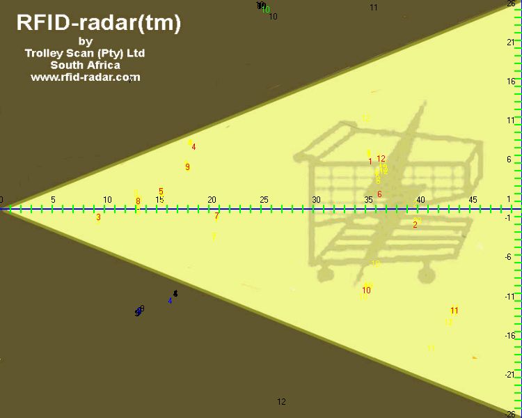
    The reader is able to resolve angles based on the spacing of the receive antennas of approximately minus 32 degrees to plus 32 degrees. If the transponder is beyond those angles, it will be reported with the opposite sign and incorrect angle.The software shows alternate positions (mirror images) if the transponder is near the edge of the vision zone.

    (In the above image the yellow zone indicates the field of view - Transponder 3 is just on the edge and its tru location and image are shown (on the other edge at the same distance). Plots in the Brown area for 1 and 7 are image locations of the plots in the yellow zone.)

    Matching the physical situation to the measurements

    Physical location of transponders

    Placement of transponders referring to display chart above


    The impact of RFID-radar on automatic identification systemns

  • This technology brings conventional RFID and RTLS technology closer together.
  • This technology encourages the development of longer range transponder technology to allow operation out to 100 meters
  • Allows solution of complex security situations, such as when a transponder crosses a fictitious boundary - like cattle moving out of a field or trolleys from a carpark.
  • Allows single radars to monitor much larger zones than multiple RFID systems.
  • Home Page

    RFIDradar / info@rfidradar.com